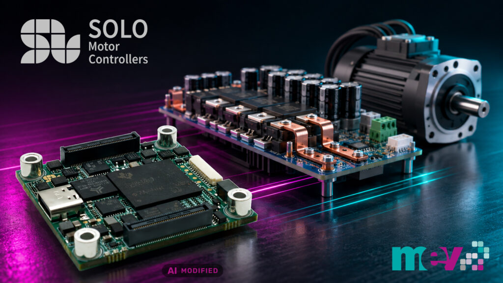
Depending on the application, electric drives place very different demands on their motor controller. Supply voltage and motor current can vary just as much as form factor, cooling, communication interfaces or the required protection functions. A standard solution is therefore not always suitable. Particularly for specialised applications, a motor controller tailored to the specific system may be necessary or economically advantageous.
Such a motor controller, however, consists of two areas with very different development requirements. On one side is the motor controller with the actual motion-control function. It not only generates the PWM signals for the power stage, but, depending on the application, also performs current, speed and position control, processes feedback from current and voltage sensors as well as position sensors, and connects the motor controller to the higher-level system via the appropriate communication interfaces. Particularly with sophisticated control methods such as field-oriented control of BLDC and PMSM motors, this results in considerable development, tuning and validation effort.
On the other side is the power stage, which must be tailored to the electrical and thermal requirements of the application. The selection and dimensioning of power semiconductors and gate drivers, current and voltage measurement, protection circuitry and thermal design depend directly on the supply voltage, motor current and required power.
While the power stage must be adapted to the voltage, current and power of the drive, the fundamental task of motor control is independent of these parameters.
Instead of treating the motor controller and power electronics as an inseparable unit for every motor-control design, the two functional areas can be designed independently. The motor controller handles motor regulation, processes the required feedback signals and provides the necessary interfaces to the higher-level system. The power stage, by contrast, is dimensioned according to the electrical and thermal requirements of the respective application.
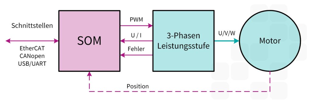
The connection between the two areas is made via defined control and feedback signals. How this functional separation is implemented technically is initially of secondary importance. The motor controller and power electronics can, for example, be located on a common PCB or implemented as separate assemblies.
The advantage of this division of tasks is that the power electronics can be tailored specifically to the application without necessarily having to change the motor-control concept as well. DC-link voltage, output current, power semiconductors, gate drivers, measurement circuits, protection functions and cooling can be dimensioned according to the required power class, while an existing solution can be used for the motion-control functions.
This is already attractive for a single motor controller: the developer can concentrate on the application-specific requirements without having to develop and validate the complete motor-control system at the same time. The benefit becomes even greater when several variants of a motor controller are required. A motion-control concept developed once can then be combined with different power stages and serve as the common basis for a product family with different voltage, current and power classes.
One way of implementing the functional separation between motor controller and power electronics is to design the complete motion-control side as an independent assembly. SOLO Motor Controllers follows this approach with the SOLO SOM. Measuring only 40 × 40 mm, the system-on-module combines the essential control, regulation and communication functions of a motor controller, while the application-specific power stage remains outside the module.
The SOLO SOM does more than calculate the motor-control algorithms. It also contains the signal processing for current, voltage and position feedback as well as the required communication functions. The developer therefore receives a largely complete motion-control platform that is connected to the power electronics via defined signals. The gate drivers and power semiconductors required for the respective application, together with current and voltage measurement, protection circuitry and thermal design, remain part of the external power stage.
The SOLO SOM has two C28x processor cores, each clocked at 200 MHz. SOLO uses one of them as the Motion Core. It executes the motor-control functions and handles, among other tasks, position-feedback processing and communication. The second core is available to the user for application-specific functions.
The Motion Core supports brushed DC motors as well as BLDC, PMSM and EC coreless motors. In addition to torque and speed control, position control is also possible. BLDC and PMSM motors can be operated either sensorlessly or with position feedback. For sensored operation, the SOLO SOM supports Hall sensors as well as incremental, absolute and Sin/Cos encoders. Functions that can require considerable implementation and tuning effort in a discrete controller solution are therefore already located on the reusable motion-control side.
The browser-based SOLO Motion Terminal is available for configuration and commissioning. It can be used to set motor, control-loop and feedback parameters and to monitor operating data.
The same applies to communication. EtherCAT and CANopen, two communication solutions widely used in industrial drive technology, are already integrated into the platform. Implementing and integrating them in an in-house development entails considerable development and validation effort. USB and UART are also available. The communication and motion-control functions remain unchanged regardless of which power electronics are combined with the SOLO SOM. A motor controller for a different voltage or power class therefore does not automatically require a new controller and communication platform. The SOM itself is not tied to a specific motor power. The voltages and currents that can actually be switched, and thus the achievable motor power, are determined by the design of the external power electronics. The respective current and voltage ranges are parameterised during commissioning so that the motor control can be adapted to the power stage being used.
To allow the same motor controller to be combined with differently dimensioned power stages, control and feedback must be clearly defined. With the SOLO SOM, a three-phase power stage is controlled via six PWM signals for the high-side and low-side switches of the three half-bridges. The SOM provides these signals at 3.3 V logic level; level adaptation and control of the power semiconductors are handled by the external gate drivers.
Depending on DC-link voltage, motor current, switching frequency and other requirements, the power stage can be designed accordingly. For motor control, the SOLO SOM in turn requires information from the power stage. The three phase currents and the DC-link current, as well as the three phase voltages and the DC-link voltage, are measured and supplied to the module as conditioned analogue signals. Hardware fault signals are also provided, for example to report overcurrent or overvoltage conditions.
Adaptation to the respective power class takes place outside the SOLO SOM. Current-sense amplifiers and voltage dividers, or corresponding measurement circuits, map the actual currents and voltages to the module’s input signal ranges. The same interface can therefore represent both small and high motor currents. The physical values corresponding to the respective measurement ranges are parameterised in software during commissioning.
In addition to signal conditioning, the interface circuitry can also implement functions such as hardware fault detection, isolation or adaptation to the gate drivers used.
While the PWM interface operates with fixed logic levels independently of the power class, the feedback signals must be adapted to the actual currents and voltages of the respective power stage. This task is performed by the external signal conditioning.
For motor control, the three phase currents and the DC-link current, as well as the three phase voltages and the DC-link voltage, are measured. The external measurement circuits adapt the signals to the SOLO SOM and are dimensioned according to the current and voltage ranges of the respective power stage. The actual values corresponding to the measurement signals are configured via the SOLO Motion Terminal.
For fast current control, however, it is not sufficient merely to bring the measurement signals to the correct level. In a PWM-controlled inverter, each switching event generates disturbances that can distort current measurement. The Motion Core therefore samples the phase currents synchronously with the PWM in the middle of the PWM cycle, once the switching transients have subsided.
This results in corresponding requirements for the analogue measurement chain. Amplifiers and filters must have settled sufficiently by the sampling instant. Depending on the application, a bandwidth between 20 kHz and 1 MHz is intended for phase-current measurement; around 300 kHz is a suitable general starting point. DC-link current and voltage measurements can, by contrast, be filtered much more strongly.
The evaluation platform for the SOLO SOM demonstrates how the concept can be transferred to different power classes in practice. Its basis is the SOLO SOM Evaluation Board, onto which the SOLO SOM is first plugged. The board provides the module’s interfaces and I/Os and at the same time serves as the connection to different power stages.
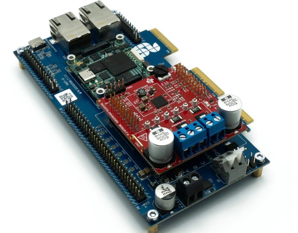
For the development of low-voltage drives, the Texas Instruments BOOSTXL-DRV8323RH can be plugged onto the Evaluation Board. The three-phase power stage operates from supply voltages of 6 to 54 V and is rated for 15 A continuous current and 20 A peak current. Current and voltage measurement are already integrated. For high-voltage applications, the same combination of SOLO SOM and Evaluation Board can be connected to a 400 V inverter platform. The motor controller and development environment therefore remain the same while the connected power electronics are exchanged.
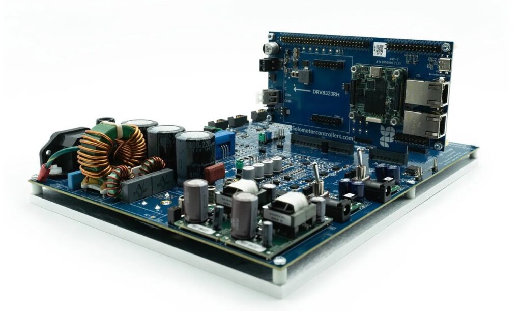
How far the concept can be scaled beyond this is demonstrated by a current motor inverter developed by SOLO with 45 kW output power, a 400 V DC-link voltage and up to 160 A output current. The same SOM also handles motor control here.
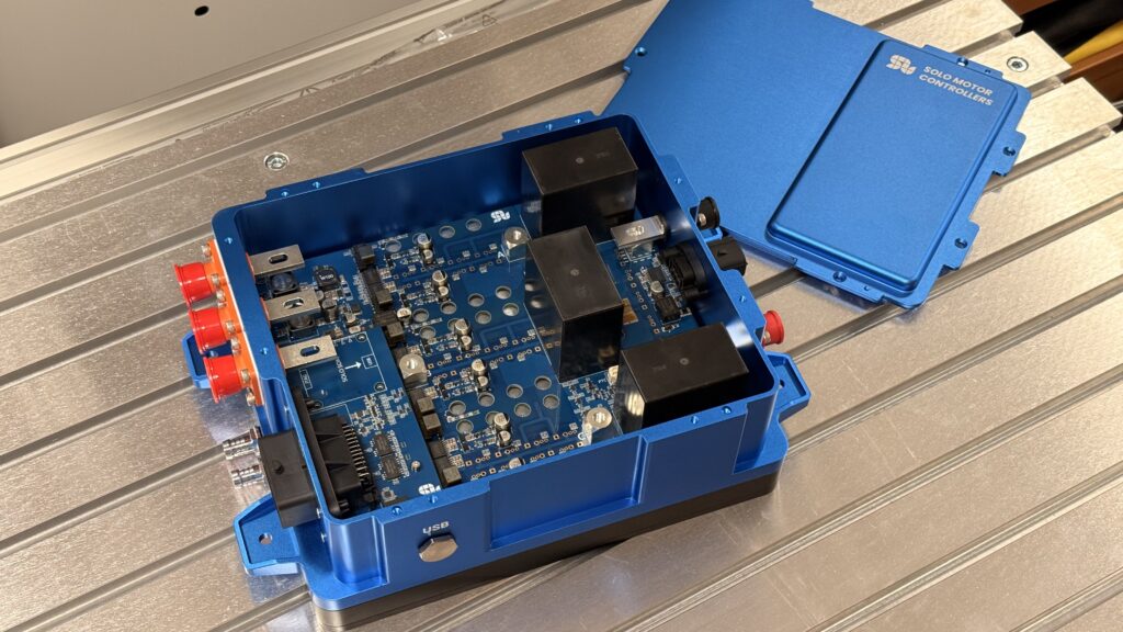
Separating the motor controller from the power stage does not mean that all monitoring and protection functions can be handled by the SOM. Particularly in high-power inverters, overcurrents or short circuits can damage the power semiconductors within a very short time. In such cases, shutdown must not depend on the motor-control software.
Fast protection functions are therefore implemented directly in the external power electronics. Critical conditions are detected there in hardware and the corresponding fault signals are transmitted to the SOLO SOM. The motor controller can then evaluate the fault, put the motor controller into a defined state and provide diagnostic information to the higher-level system. Fast hardware-based protection functions and additional firmware monitoring functions therefore complement each other.
The intended hardware fault indications include overcurrent, overvoltage, undervoltage and overtemperature.
Functional safety is also taken into account: a Safe Torque Off (STO) function can be integrated into the concept. The SOLO SOM provides two independent STO channels and handles their monitoring and diagnostics. The actual safety-related shutdown, however, takes place outside the controller directly in the power electronics, for example by interrupting the gate-driver supply.
The separation of motion control and power electronics opens up different routes for implementing a motor controller. The user can develop the power stage in-house and tailor it specifically to requirements regarding voltage, current, power semiconductors, form factor and cooling.
Alternatively, development of the power electronics can be outsourced. SOLO develops customised motor controllers and can combine the SOLO SOM with a power stage tailored to the respective application.
In addition to the Motion Core reserved for motor control, the SOM has a second C28x processor core, also clocked at 200 MHz. This is available to the user for application-specific functions. Additional tasks can therefore be executed directly on the SOLO SOM without interfering with the motor-control software provided by SOLO.
The tasks handled by the second core depend on the respective application. In the field of power electronics, it can, for example, control a DC/DC converter or a PFC stage. Additional PWM outputs and analogue inputs are available for such time-critical control tasks; the PWM units can operate at frequencies of up to 1 MHz.
Separating motion control and power electronics makes it possible to consider the complex motor-control function independently of the required power class. With the SOLO SOM, SOLO implements this principle as a compact, reusable platform, while the power stage can be tailored specifically to the respective application.
The approach is therefore suitable both for developing a single motor controller and as a common basis for a product family with different voltage and power classes. The spectrum ranges from compact low-voltage drives to motor controllers in the tens-of-kilowatts range. The freely programmable second processor core also provides the option of integrating additional application-specific functions on the same platform.
SOLO Motor Controllers was founded in 2019 in Lombardy, Italy, and develops solutions for electric drive technology. The company focuses on three business areas: standard modules, customised solutions and motor test benches.
The standard-module portfolio includes complete motor controllers and the SOM presented in this article.
MEV will present the SOLO SOM at SPS 2026 in Nuremberg from November 24 to 26. Hall 4, Booth 174. You are welcome to schedule an appointment and request your free ticket in advance!

SOLO SOM User Manual (EN, PDF)
Guido Gandolfo
Product Line Manager
Motion Control
+49 5424 2340-57
ggandolfo@mev-elektronik.com


