For whitepaper download, please scroll down to the bottom.
With smart motor drives that boost productivity and improve operational costs even further, Industrial Automation is empowered by intelligence at the edge. This means more and more data is processed at the edge, including sensors, cameras, and actuators, taking low-level, real-time decisions while providing aggregated data for higher controls.
For actuators to gather and process data at the edge, it is important that the system has a clear picture of normal operating conditions. Take friction for example. If a conveyor belt is running without a component on it, the actuator experiences a certain amount of friction which is affected by several factors including length and weight of the belt itself. But what if this friction increases? Does it indicate possible wear and tear within the system, or is it simply because several components were placed on the belt? Tuning motor controllers is a fundamental step for generating a clear picture of normal operating conditions, one that can be sped up with the correct tools.
First, of all motor drives, those using field-oriented control (FOC), or vector control, arguably offer the highest performance. Tuning FOC, however, can be laborious and puts a huge strain on resources during application development. In particular, tuning the P and I parameters require expert know-how. Not only during initial setup, also when the application’s parameters need to be adjusted to meet consumer demands.
Second, the frontier of Industrial Automation is marked by increasingly complex machines where drive systems and sensors at the edge are gathering information and interacting with each other. This increases overall complexity, pulling resources away from other aspects including motor and motion control in favor of development of the application and hardware abstraction layer. Moreover, increased complexity adds factors taken into account when tuning the motor, thereby putting more strain on the Engineer tuning the controller.
Third, with increased interaction and complexity of the machine, a new generation of machines is introduced at the frontier of Industrial Automation. A generation that comes with “a built-in fail-safe mechanism that automatically detects an operational problem preventing it from completing its assigned task. It then initiates steps to temporarily transfer its given task to other machines in the work cell until the faulty machine can be repaired.”
The fourth argument for auto-tuning is to quickly compensate for manufacturing tolerances in series production. Even with improved assembly lines, not every machine will be 100 percent according to spec. Correcting a motor drive for the system’s deviation originating from the assembly line would, again, put a huge strain on resources. That is, of course, if there’s no auto-tuning tool offered for the motor controller.
Finally, auto-tuning tools further democratize technology and therefore boost innovation. Already since years there’s a visible trend where electronic components are becoming cheaper. Take for example high-quality BLDC motors, once exclusively used for high-end machines until drones went commercial and BLDC motors became a mass product. With lowered component prices, these parts suddenly became interesting in other fields as well, boosting product development and breakthroughs in other devices. By making not only the components, but also the know-how more accessible, tools automating motor controller tuning give another impulse to innovation. Either because it makes new technology accessible to those companies who wouldn’t be able to implement it otherwise, or because it frees up precious resources including experts who can now focus on ground-breaking features and devices.
The first step of auto-tuning a BLDC drive is similar to manually tuning one, which is identifying the tuning parameters for PI controllers in the application. These tuning parameters vary per application and can even vary within an application per working point. Examples are maximum torque and speed, which are dependent on the motor load, and positioning. For identifying and optimizing these parameters, the real setup is needed – or a realistic model of the electromechanical system which takes all factors into account. The benefit of such an approach, compared to tuning PI controllers on the bench, is that external parameters are considered as well. These include backlash, friction, and inertia to name a few.
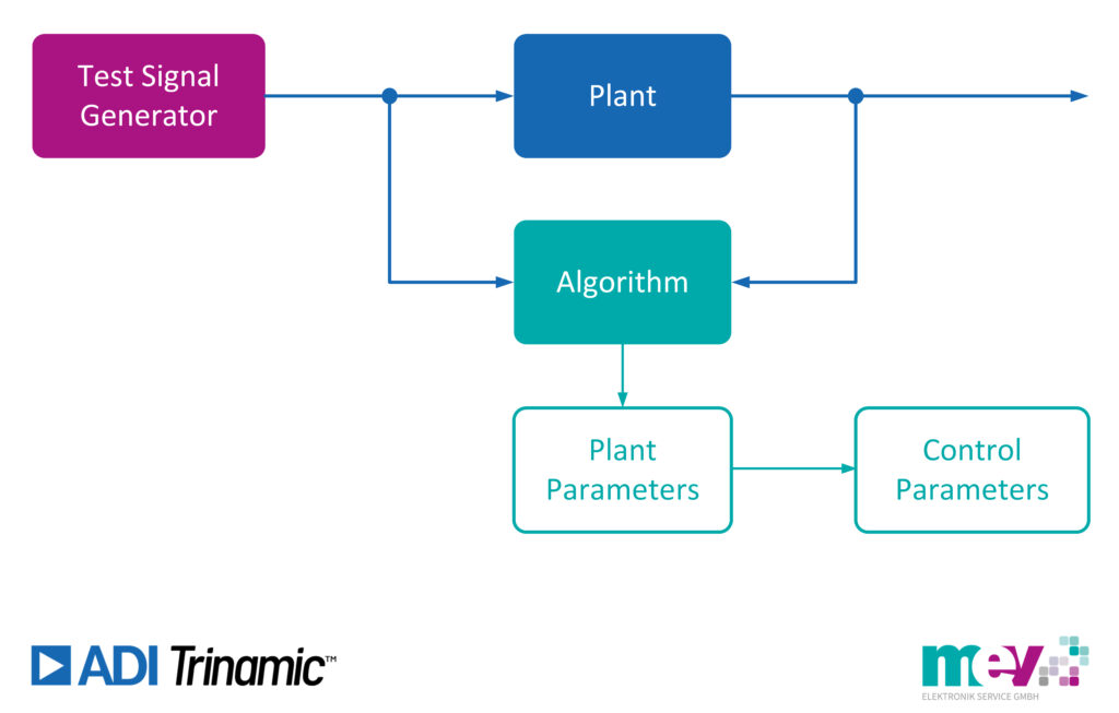
One way of identifying these parameters and finding the application limits is using a test signal injection and correlation. Simply put, you send a test signal through the system, measure the output and feed it to an algorithm, which then calculates the optimal parameters. Once calculated, this will be fed through the system again for a plausibility check, validating the calculated parameters. However, there is another method of identifying these parameters, following the more practical approach of traditional manual tuning done by experts.
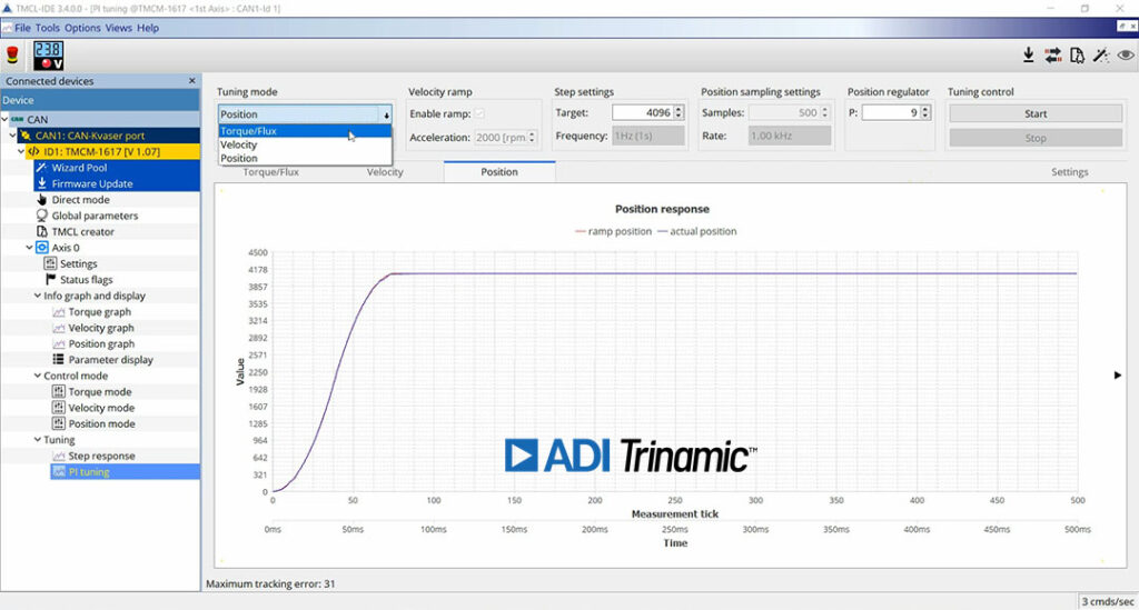
To speed up motor drive commissioning, Trinamic developed a graphical tuning tool for their latest generation of modules using the integrated servo controller IC TMC4671. This tool is available free of charge in Trinamic’s integrated development environment (TMCL-IDE), with the main goal to tune the P and I parameter of the cascaded motor control structure automatically.
This tuning process works as follows: at first, the parameter of the FOC current loop, secondly the velocity and finally the position control loop are tuned. During the tuning process, step or ramp inputs to the drive’s cascaded control loops are applied. The response is measured in the module and the TMCL-IDE tool iteratively increases the controller gains to optimize the tracking performance and dynamics. The tool guides the user through this process step-by-step and the engineers can monitor the result of each iteration. Ideally, the setup is tuned within the application and the motor can rotate freely.
At first, the parameter of the FOC current control loop, as the most inner and faster loop, are optimized. Therefore, a step generator for the target current applies defined current steps to the FOC controller. The value of the step can be chosen according to the operation point of the user’s application. The tuning tool visualizes the target values and the responses and uses the data to decide how to enhance the controller behavior. It then updates the FOC current loop P and I parameter automatically until a minimum controller error is achieved and the current loop tuning process finishes.
The second step is the tuning of the velocity control loop. During this process, the velocity ramp can be used, and the acceleration can be set according to the application needs. The user can select the target velocity to which the P and I parameter of the velocity control loop should fit best. Then, the signal generator in the tuning tool generates target velocity steps. The actual velocity response of the motor is measured, and the P and I parameter are updated constantly. After the velocity error has been minimized, the velocity auto-tuning is completed.
As a final step, the position control loop P parameter will be optimized. Therefore, the motor performs target position steps, the actual position is measured, and the tuning algorithm adjusts the P parameter until a minimal position following error is derived.
The resulting P and I values from the auto-tuning process can also be tested and adjusted in the manual mode of this tool. In this mode, continuous step responses for the position, velocity, or current loop can be simulated and the resulting actual values of all controllers can be monitored and used to adjust the P and I parameter on the fly.
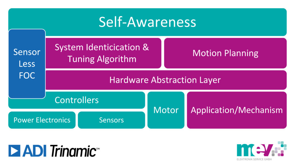
For machines to independently adapt its performance parameters and complete an assigned task, or re-configure themselves for optimized behavior based on input from a productivity enhanced AI observer algorithm, auto-tuning is the only option. This can be achieved by monitoring and auto-tuning the P and I values derived from the three cascaded FOC loops used to optimize the drive’s torque-flux current loop, velocity loop settings, and its positioning loop parameters. Perfect tuning of controllers, therefore, will no longer be defined by its settings during initial setup. Instead, it requires constant monitoring and adaptation.
With the intuitive auto-tuning tool, Trinamic’s latest generation of motor drives take a first step of becoming smart systems, eventually paving the way for the self-aware machines marking the next revolution in Industrial Automation. Auto-tuning will prove to be crucial for this next breakthrough, both for initial setup and for re-configuration of equipment to optimize its behavior. By continuously monitoring torque, velocity, and position parameters and comparing these to a model, the drive adapts or flags incoherent data. As such, the actuator becomes an additional sensor, empowering intelligence at the edge.
The next evolution of Industrial Automation brings self-aware machines for maximized productivity, extended operational lifespan, and reduced maintenance costs. This calls for motor and motion controllers with a high level of integration that can determine if everything behaves accordingly or if performance parameters need to be changed on the fly by reconfiguring themselves. Once tuned to perfection via auto-tuning, motor controllers can monitor for both internal issues, such as wire breaks or degraded power stage impedance, and external processes affecting the application’s behavior such as friction, inertia, temperature, and backlash.
By not only using the data gathered at the edge for auto-tuning purposes but aggregate it together with data from external components in data packets that are distributed throughout other machines on the factory floor, Industrial Automation takes an important step into the future. Think of machines working together in a manufacturing cell. Each machine has been assigned a specific task in the assembly line needed to produce a product. If a machine in this cell experiences a problem performing its specific task, then the production line would shut down until it can be serviced. Now let’s imagine this same scenario using machines that are self-aware enabled. In this scenario, the other machines in the manufacturing cell would realize one machine is not performing its task and then automatically off-load the specific function of the problematic machine temporarily to the other machines in the cell to keep the production line running until a technician is available to fix the problematic machine. Auto-tuning may seem like a small step. With Trinamic, however, it’s the first step to self-aware machines.
If you have questions regarding ADI Trinamic’s Auto-Tuning please contact:
Guido Gandolfo, Product Line Manager Motion Control
+49 5424 2340-57
ggandolfo@mev-elektronik.com


