Industrial automation is developing rapidly – flexible production environments, autonomous material flows, and safe human-machine collaboration are now decisive competitive factors.
In the brochure “Robotics – Cobots & AGVs”, we present MEV Elektronik’s product portfolio, which has been specially compiled for these applications. From powerful semiconductor solutions to sensor technology and power supplies to communication and interface modules – MEV offers the right components for precise, efficient, and fast robotics systems.
Discover innovative technologies from our areas of expertise in Motion Control, Sensors, Networking/Datacom, RF Microwave/Wireless, Storage, and Power Management—ideally suited for Collaborative Robots and Automated Guided Vehicles.
MEV Elektronik – Your partner for intelligent automation solutions.
The individual product groups are linked to our website. Simply click on the desired product area in the tables.
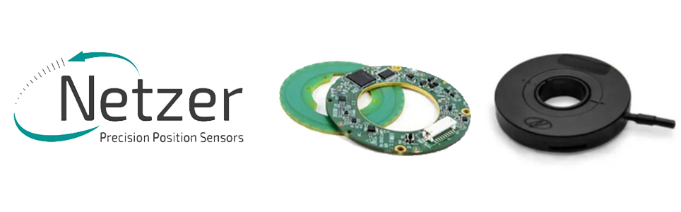
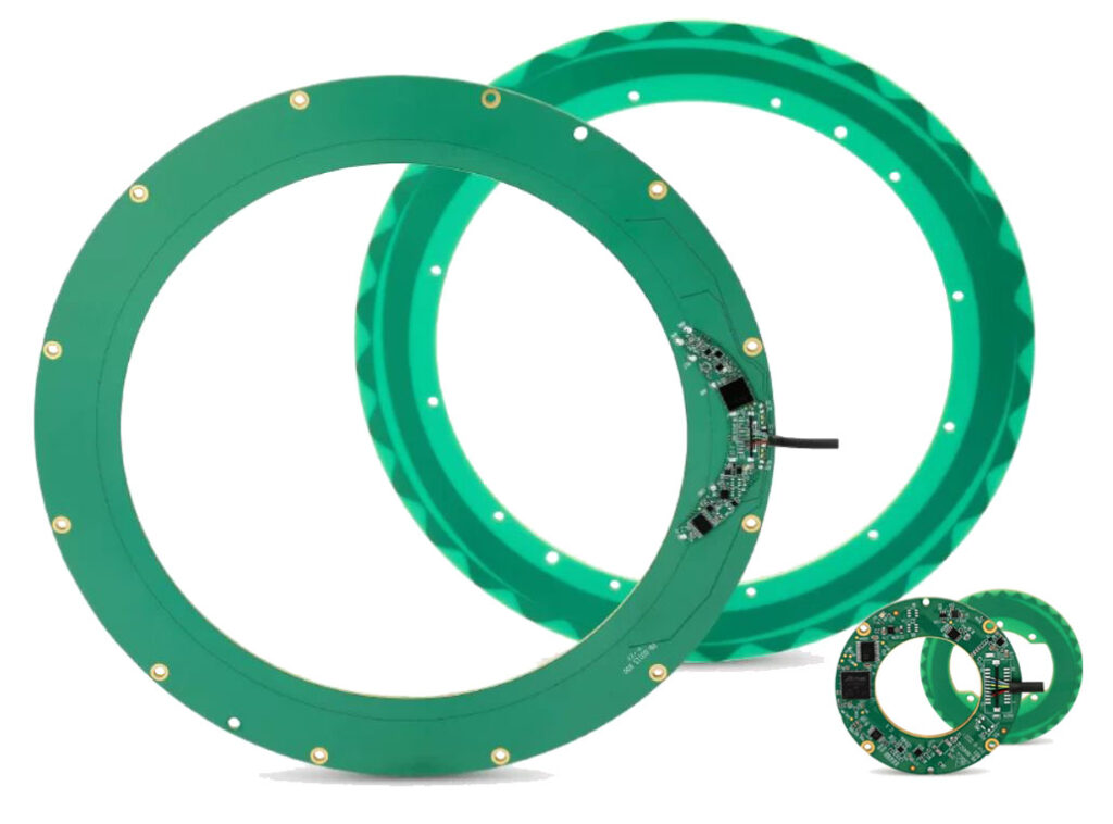
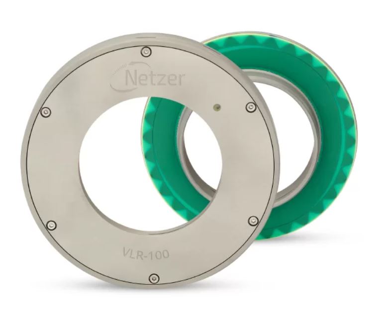
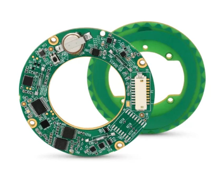
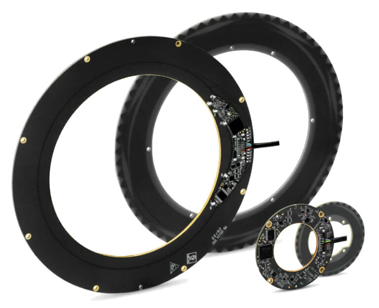
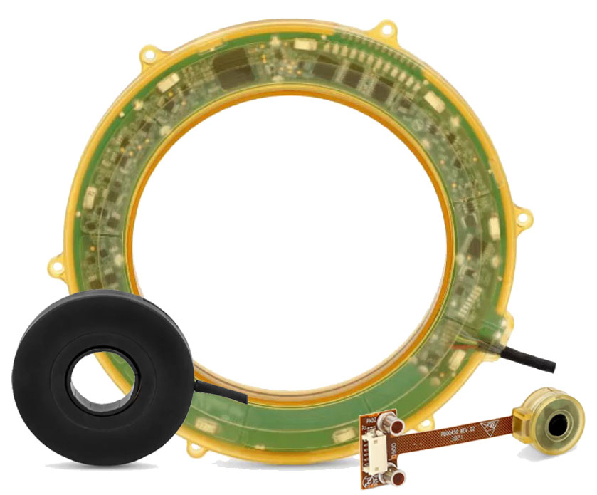
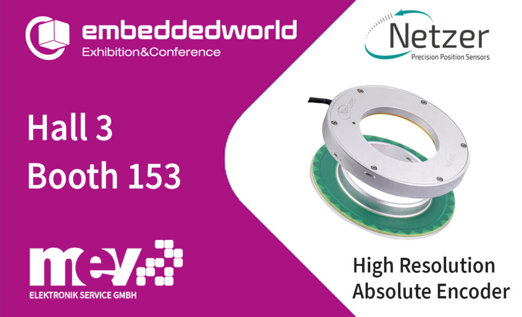
High-resolution absolute encoders from Netzer Precision.
The Electric Encoder™ – the line of capacitive absolute rotary encoders patented by Netzer Precision Position Sensors. The line of the robust and reliable Electric Encoders™ includes both analog and digital, standard or customized, high-Performance absolute rotary encoders which are suitable for applications ranging from space and avionics, harsh environment, as well as industrial, instrumentation, medical and automotive applications.
The Electric Encoder’s unique hollow-shaft contactless structure, meets the minimum possible space requirements and enhances reliability by eliminating degradation and failure mechanisms. The advanced Electric Encoders™ adds intelligence to positionsensing and its high capabilities makes it a leading sensor to integrate with modern motion control applications, meeting their strict requirements.
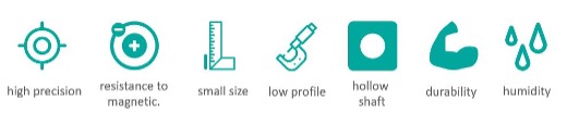
In addition to an extremely flat design, the capacitive hollow shaft encoders also offer very good EMC and are suitable for harsh environments.
Features:
High resolution 16 to 26 bit
High accuracy 0.001° – 0.020° / repeatability ±1 count
Very good EMV
Small size, flat design
hollow shaft
Suitable for harsh environments (shock, vibration, temperature, etc.)
SSI & BISS interface
Due to their properties, Netzer’s Electric Encoders™ are very well suited for the following applications / markets:
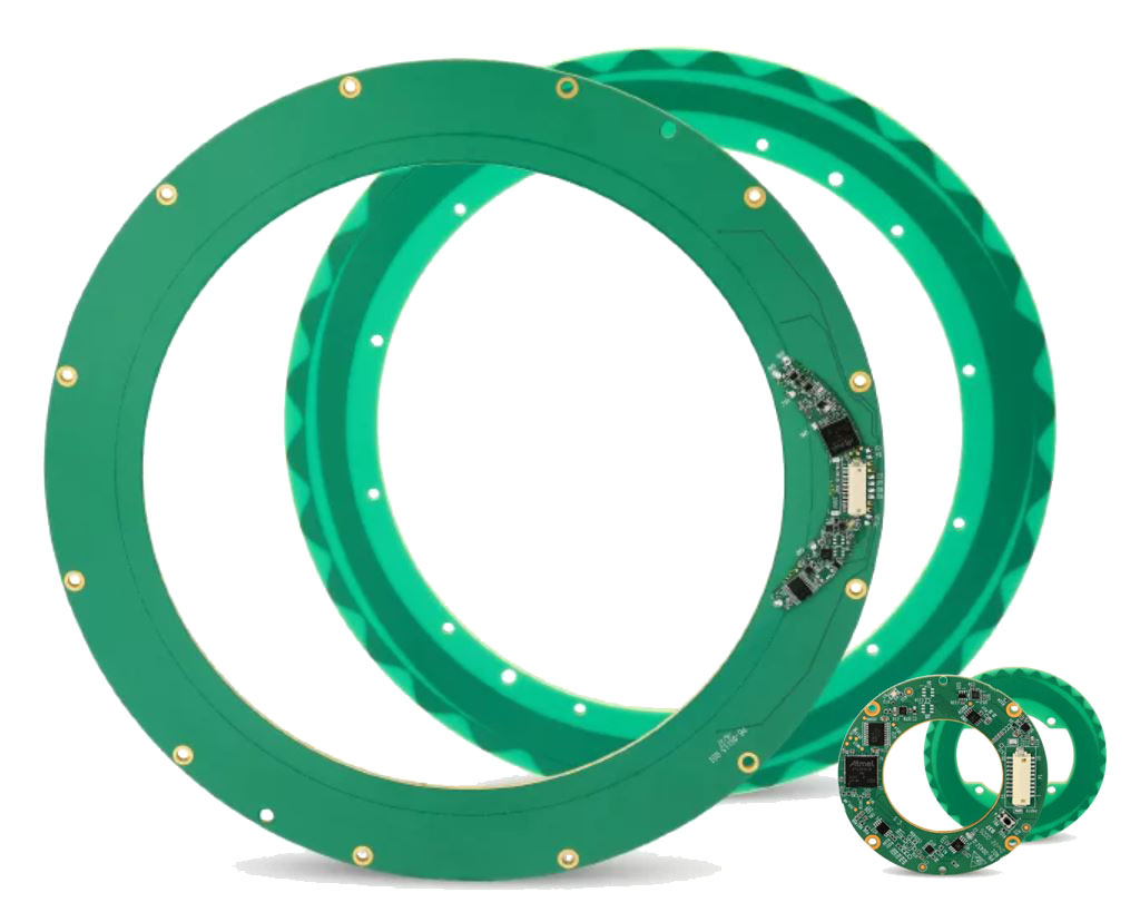
The following product series are currently available:
VLX-series: Hollow Shaft Capacitive Absolute Encoders (25…247mm), Robotics and Automation
You can get more information by clicking on the series or the pictures!
High-resolution absolute encoders from Netzer Precision will be presented at Embedded World show in Nuremberg (10 MAR to 12 MAR 2026) at the MEV booth 153 in hall 3. You are welcome to book an appointment in advance.
embeddedworld is just around the corner – bringing with it exciting new solutions and products!
The following product highlights and more will be presented at our exhibition booth this year:
Your partner for advanced display solutions.
E-paper, TFT, LCD and OLED – innovative display technologies for industrial, medical, railway and transportation systems as well as other professional applications. Our experts support you from the initial idea to the optimal display solution. Visit us at the trade fair, explore new possibilities and get personal advice.
5G-NR Advanced Connectivity with CQM212 and CQM215 from Cavli Wireless
“Cavli Wireless presents the CQM212 and CQM215 5G-NR Advanced Sub-6 GHz cellular modules, developed to meet the performance and integration demands of modern IoT and M2M applications. Both modules are compliant with 3GPP Release 18 and support LTE Cat 20 fallback, ensuring robust, backward-compatible connectivity across global deployments. The modules integrate a quad-core Arm Cortex-A55 processor running Linux. With support for up to 2 GB of LPDDR5 memory and 2 GB of NAND storage, they simplify system architecture and reduce overall design complexity. Integrated multi-constellation GNSS enables accurate positioning for tracking and location-based applications. The CQM212 supports up to 3x carrier aggregation, while CQM215 extends this to 4x carrier aggregation, achieving peak 5G downlink speeds of up to 7.01 Gbps. Featuring broad-band coverage, PCIe Gen 4 and USB interfaces, and an LGA form factor, the CQM212 and CQM215 provide a scalable and future-ready connectivity platform for industrial, smart infrastructure, and high-bandwidth IoT solutions.”
New: Sparklan WiFi 7 WNFQ-293BE(BT) and WNSQ-293BE(BT) – perfect for AI and embedded systems
“The new SparkLAN Wi-Fi 7 modules WNFQ-293BE(BT) and WNSQ-293BE(BT) offer high-performance tri-band connectivity (2.4/5/6 GHz) and are specifically designed for demanding edge, industrial, and AIoT applications. Available as M.2-2230 plug-in modules and M.2 LGA-1620 solder-on modules, they support both x86 and ARM platforms.
Features such as Multi-Link Operation (MLO), 160 MHz bandwidth, and 4096-QAM modulation enable extremely fast, stable, and low-latency connections – even in congested or mission-critical environments. PCIe (WLAN), USB/UART (Bluetooth 5.4), and Linux driver support allow for flexible integration of the modules. They are ideally suited for AI controllers, industrial gateways, robotics, smart mobility and other intelligent edge systems.”
Realtek IoT Wi-Fi & Bluetooth Solutions
“Realtek offers a broad portfolio of IoT connectivity solutions, including highly integrated Wi-Fi and Bluetooth SoCs from the Ameba family, as well as Bluetooth-only chips for energy-efficient wireless applications. The Ameba series comprises high-performance IoT SoCs with integrated Wi-Fi connectivity (802.11 b/g/n, dual-band depending on the variant) and Bluetooth Low Energy (BLE). These SoCs combine wireless technology with ARM- or RISC-V-based microcontrollers, extensive peripherals (UART, SPI, I²C, PWM, ADC, GPIO, and some USB). Integrated security features, making them ideal for compact, networked embedded systems with reduced bill of materials (BOM) requirements. In addition, Realtek offers Bluetooth-only chips optimized for low-power BLE-based communication, making them particularly suitable for wearables, sensors, wireless control units, and simple IoT devices. A comprehensive software and development ecosystem with SDKs, reference designs and RTOS support enables rapid development and easy integration of modern IoT applications.”
Realtek Low Latency PHY
With the RTL8201HE and RTL8211G, our partner REALTEK is launching two new Ethernet PHYs that are suitable for automation applications (EtherCAT, PROFINET, etc.) due to their low latency. The RTL8201HE supports Fast Ethernet, is available in QFN24, and can be used up to +105°C. The RTL8211G supports Gigabit Ethernet, is available in QFN32, and can be used up to +85°C.
Realtek Low Power 10GB PHY
Our partner REALTEK, market leader in Ethernet PHYs, offers products for all relevant data rates: FE, Gigabit, 2.5Gb, 5Gb, and 10Gb. One highlight is RTL8261D which supports up to 10Gb, in an 8x8mm QFN56 package. Power consumption is very low: just 1.48W. Industrial Temperature, IEEE1588.. etc.. are available.
Next-Generation Linear Position Sensing.
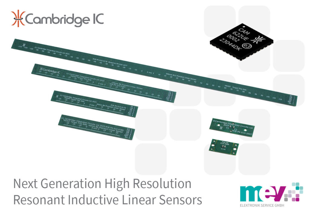
MEV Elektronik presents CambridgeIC’s innovative new range of resonant inductive Linear Sensors Type B. These sensors combine robustness, precision, reliability, and low cost, thanks to their manufacture using a conventional PCB process.
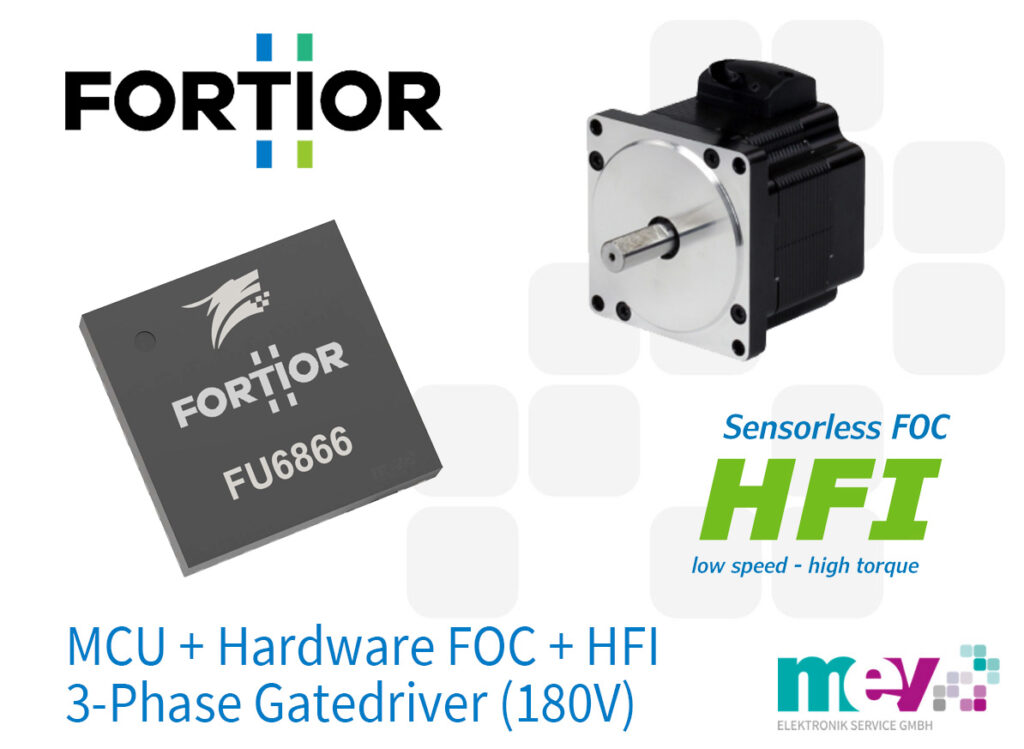
BLDC motor IC with HFI for impressive low-speed torque with sensorless FOC.
MEV presents the FU6866 BLDC controller IC from Fortior Technology. It integrates state-of-the-art High Frequency Injection (HFI) technology to ensure high torque even at low speeds, setting new standards in motor control applications.
16-bit hall magnetic angle sensor ICs with automatic non-linear calibration (ANLC) and low error.
MEV introduces the Conntek KTH7111 and KTH7112 encoder ICs. Both devices set new standards in precision and ease of integration thanks to patented Automatic Non-Linear Calibration (ANLC) technology, which automatically compensates for mounting and magnet variations, ensuring exceptionally high accuracy.
The world’s smallest IO-Link device transceiver
MEV Elektronik presents Nisshinbo‘s ND1160 for applications with limited installation space.
The ND1160 sets new standards in industrial automation and sensor communication – with its compact design, robust functionality, and full IO-Link standard compliance.
The ND1160 was developed specifically for modern industrial sensor and automation applications and supports the IO-Link data rates COM1, COM2, and COM3. With its ability to operate in high-side, low-side, and push-pull modes, it offers a flexible interface for a wide variety of platforms and facilitates integration into existing systems. With a wide operating voltage range from 8.5 V to 36 V and an output current of at least 200 mA, the transceiver is both powerful and versatile.
Strategic Technology Milestone – Wolfspeed has produced a single crystal 300mm (12-inch) silicon carbide wafer, representing a major advancement in the evolution of silicon carbide technology and a critical enabler for emerging applications.
Technology leadership for Next-Gen Applications – Backed by one of the industry’s largest and most foundational silicon carbide IP portfolios, with over 2,300 issued and pending patents worldwide, Wolfspeed is accelerating the commercialization of 300mm technology to power next-generation platforms including AI infrastructure, augmented reality/virtual reality (AR/VR) and advanced power devices.
Strengthening U.S. Semiconductor Leadership & Supply Chain Resilience –The company’s vertically integrated supply chain, from crystal growth to advanced packaging, supports national goals around compound semiconductor independence, AI competitiveness, and secure domestic access to critical technologies.
MEV Elektronik presents Nisshinbo‘s ND1160 for applications with limited installation space.
The ND1160 sets new standards in industrial automation and sensor communication – with its compact design, robust functionality, and full IO-Link standard compliance.
The ND1160 was developed specifically for modern industrial sensor and automation applications and supports the IO-Link data rates COM1, COM2, and COM3. With its ability to operate in high-side, low-side, and push-pull modes, it offers a flexible interface for a wide variety of platforms and facilitates integration into existing systems. With a wide operating voltage range from 8.5 V to 36 V and an output current of at least 200 mA, the transceiver is both powerful and versatile.
The ND1160 is available in a 3 x 3 mm DFN or 1,76 x 2,26 mm WLCSP package.
Thanks to integrated protection mechanisms such as overcurrent, thermal shutdown, and reverse polarity protection, the ND1160 offers high reliability—a decisive advantage in demanding manufacturing environments.
“We are proud to offer our customers the ND1160 from Nisshinbo, an IO-Link solution that not only impresses with its technology, but also offers maximum flexibility and ease of integration“, explains Guido Gandolfo, Product Line Manager at MEV. “The ND1160 with its small housing opens up new possibilities, especially for developers with limited installation space – both in sensor and actuator systems.“
MEV Elektronik supports its customers with technical advice, evaluation boards, and samples of the ND1160 to accelerate development processes and facilitate the market launch of innovative products.
The IO-Link Device Transceiver ND1160 will be presented at Embedded World show in Nuremberg (10 MAR to 12 MAR 2026) at the MEV booth 153 in hall 3. You are welcome to book an appointment in advance.
About Nisshinbo
Nisshinbo is a global technology group headquartered in Japan. The company develops and manufactures innovative solutions in the fields of electronics, microelectronics, automotive technology, industrial applications, and energy efficiency. With a strong focus on quality, reliability, and sustainable innovation, Nisshinbo serves customers worldwide and supports the development of future-oriented products and systems.
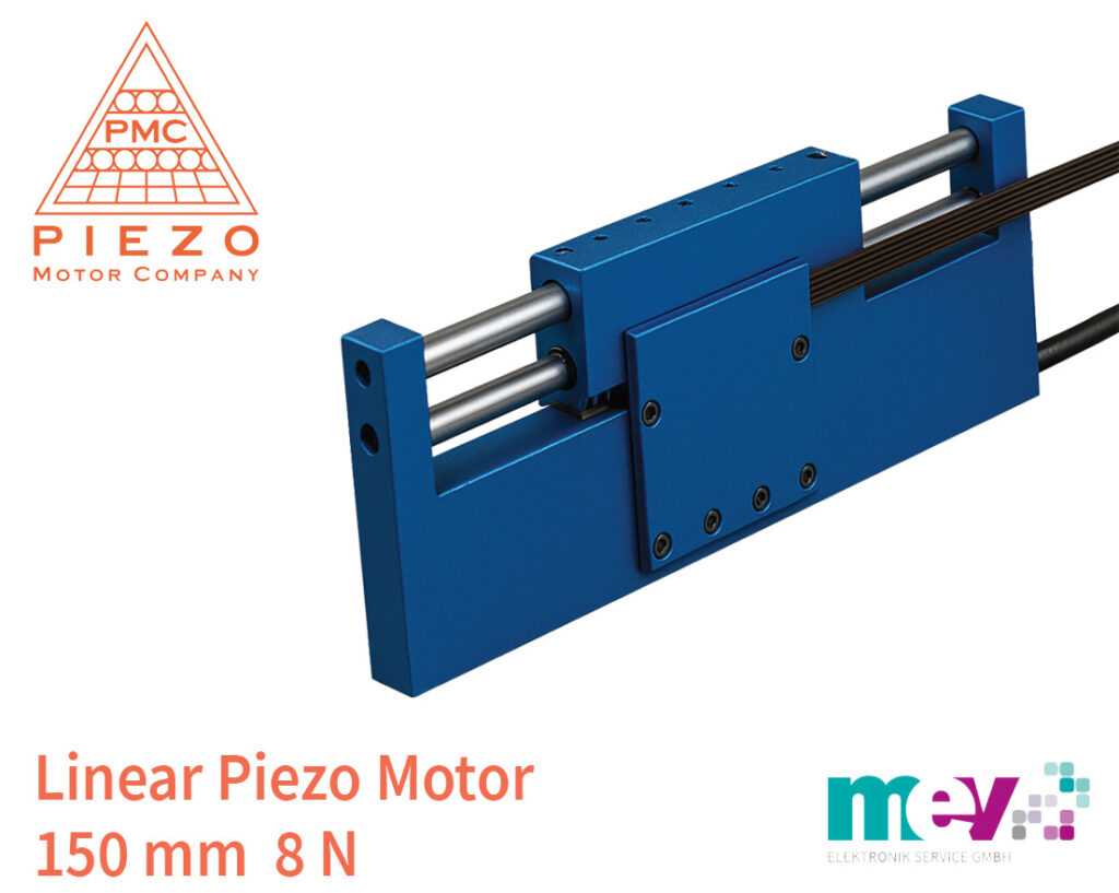
LRMO-150 Linear Piezo Motor – Precision Motion Redefined.
MEV introduces the LRMO-150 Linear Piezo Motor from Piezo Motor Company (PMC). This innovative actuator represents a significant advancement in compact linear motion technology, combining micrometer precision, fast response, and energy-efficient operation for demanding industrial and scientific applications.
Next-Generation Linear Motion Performance
The LRMO-150 is part of PMC’s newest series of piezoelectric linear motors, designed to deliver unmatched motion control performance. Featuring an extended stroke of 150 mm (with custom lengths available), the LRMO-150 offers an open-loop step size of just 0.04 µm, enabling 25,000 precise steps per millimeter of linear travel. In closed-loop operation, with an optional factory-fitted magnetic encoder, the motor achieves a controlled step size of 2.6 µm and uni-directional repeatability of the same order.
With a high dynamic speed range and zero power consumption in holding mode, the LRMO-150 provides a superior balance of speed, precision, and energy efficiency. Its electromagnetic immunity and non-magnetic construction make it ideal for use in MRI environments, optical instruments, metrology, and precision robotics.
Advanced Control Architecture with the Electronic PCB Driver
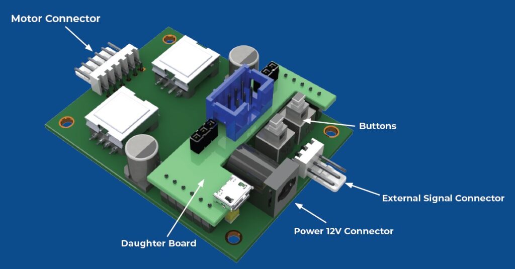
Each LRMO-150 motor is paired with a dedicated Electronic PCB Driver (model ROLR-150-PCB or ROLR-150-CL-PCB for encoder versions). This compact 12 V driver board converts user input commands into the precise electrical waveforms needed to excite the piezo resonator, enabling smooth motion in both stepping and continuous modes.
Control options
Open-Loop Operation via PWM control signals for external controllers
Closed-Loop Operation with serial interfacing and feedback using the PMC encoder
Software Integration: Compatible with PMC’s Motor Control Software and Python API for easy integration into embedded systems
Evaluation Kits available, including motor, driver PCB, cables, and power supply
The driver’s pre-programmed motion algorithms and configurable frequency and amplitude profiles simplify system design and reduce time-to-market for OEM customers.
Advantages for MEV and Its Customers
The collaboration between MEV Elektronik and Piezo Motor Company combines leading-edge technology with local engineering support and European market expertise. For MEV customers, the LRMO-150 offers:
Access to ultra-precise linear motion with nanometer-level resolution
Simple system integration using the compact 12 V Electronic PCB Driver
Superior energy efficiency, consuming only 0.5 W at 1 mm/s and zero power in hold position
Silent, vibration-free operation ideal for medical, laboratory, and optical systems
EMI and RF immunity for use in sensitive environments
“The LRMO-150 perfectly embodies the evolution of modern motion control — precision, speed, and intelligence in one compact package,” said Guido Gandolfo, Product Line Manager at MEV Elektronik. “With PMC’s advanced driver technology and piezo design expertise, we can now offer our customers a solution that outperforms traditional stepper or servo mechanisms in every aspect.”
Availability & Outlook
The LRMO-150 is now available to order from MEV. Technical information, application data, and samples can be requested directly from the sales department or via the website.
About Piezo Motor Company (PMC)
Founded in 2024 and headquartered in Boca Raton, Florida (USA), Piezo Motor Company LLC is dedicated to advancing the capabilities of piezoelectric motion systems. PMC’s portfolio includes linear and rotary piezo motors, drivers, and custom actuator solutions designed for medical devices, aerospace, robotics, and precision instrumentation. With a strong focus on research and innovation, PMC combines deep material science knowledge with state-of-the-art control electronics to deliver reliable, compact, and high-performance motion components.
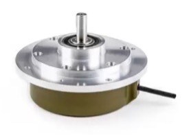
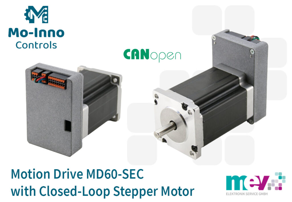
MD60-SEC is the name of the new family of mechatronic drive units with closed-loop stepper motors from Mo-Inno Controls. The system combines precise control, high torque density, and a compact design – ideal for demanding automation tasks in device and machine construction.
Compact drive with integrated intelligence
The MD60-SEC family from Mo-Inno Controls (founded by Mocontronic employees) combines motor, encoder, and controller in a single, robust component. The integrated closed-loop control method offers the highest dynamic performance and position accuracy, prevents step losses, and ensures maximum smoothness even under varying load conditions. A so-called torque mode is also available, in which the stepper motor applies an adjustable torque without movement.
The series is available in two versions with 2.1 Nm and 3.0 Nm holding torque.
Technische Highlights
Closed loop stepper motor – Prevents step losses and ensures precise position feedback.
High-resolution 16-bit encoder – For precise and fast position control.
Load-dependent current control – Optimizes energy consumption and reduces heat generation.
Stand-alone or host operation – Operation can be controlled either independently (customer-specific sequence control) or via CANopen.
Versatile interfaces – CANopen (optional USB or RS-485) for easy system integration.
PLC-compatible I/Os – Short-circuit-proof digital and analog inputs and outputs (24 V / 0-10 V).
Flexible connection options – Crimp, push-in, M8, or M12 connectors for industrial integration.
Standard mounting – 60 x 60 mm motor flange in NEMA 24 standard.
Optional metal housings – Available in various IP protection classes for EMC-compliant operation.
This combination of performance and precision makes the MD60-SEC family the ideal solution for applications where compact design, repeatability and efficiency are paramount.
Significance for MEV and its customers
With the addition of the MD60-SEC family to its product range, MEV is strengthening its position in the field of mechatronic drive systems. The MD60-SEC family optimally complements the existing motion control portfolio and offers customers a practical solution that reduces development effort, space requirements, and integration costs.
“With the MD60-SEC family, we are expanding our offering with a powerful, controlled stepper motor solution that combines maximum precision and flexibility,” explains Guido Gandolfo, Product Line Manager for Motion Control at MEV. “The closed-loop approach offers real added value, especially for applications with high demands on dynamics and efficiency – and underscores our commitment to always offering customers the most modern and best solutions.“
Availability & Outlook
The 2.1 Nm and 3.0 Nm variants of the MD60-SEC family are now available to order from MEV. Technical data sheets, application notes, and samples can be requested directly from the sales department or via the website.
About Mo-Inno Controls
Mo-Inno Controls GmbH specializes in drive technology, based in Hamburg with a development center in Berlin. The company develops and manufactures hardware, firmware, and software-based components and systems for mechanical and equipment engineering, as well as industrial automation solutions. Mo-Inno Controls’ expertise lies particularly in the integration of control electronics and drive technology, as well as in the development of intelligent, networked components. This focus creates innovative products that can be directly used in complex applications.
Downloads & Links
Contact
If you would like to know more about MD60-SEC family, please contact:
MEV Elektronik presents CambridgeIC’s innovative new range of resonant inductive Linear Sensors Type B. These sensors combine robustness, precision, reliability, and low cost, thanks to their manufacture using a conventional PCB process.
The new Linear Sensors Type B incorporate special coil designs from CambridgeIC. Currently available designs support measuring lengths of 40 mm, 50 mm, 100 mm, and 200 mm. Each sensor includes an excitation coil to energize the target, coarse sensor coils to establish absolute position, and fine sensor coils for precision and accuracy.
Efficient and Flexible Manufacturing
A key benefit of this design is that customers can manufacture the sensors themselves using design data provided by CambridgeIC. This approach helps to reduce production costs while maintaining full control over manufacturing.
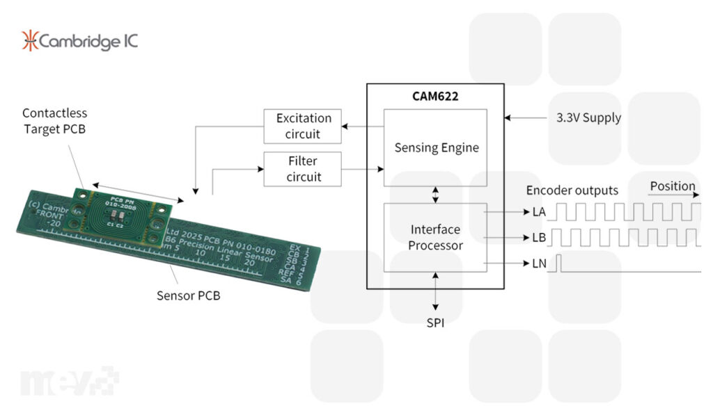
The sensors detect the position of a moving, contactless target, which is also realised as a PCB comprising a resonant circuit with a printed coil and capacitor(s). This resonant target design generates substantially stronger signals than conventional inductive sensors, enabling high resolution, superior accuracy, wide operating gaps, and calibration-free operation.
Advanced Signal Processing with CAM622
The signal processing of the Linear Sensors Type B is handled by CambridgeIC’s CAM622 Resonant Inductive Position Encoder IC. The CAM622 provides:
SPI interface, delivering typically 1 μm noise-free resolution and full absolute position
Quadrature ABN interface, configurable down to 2 μm AB edge resolution
Newly announced BiSS-C interface support (BiSS is a trademark of iC-Haus GmbH).
With these features, CambridgeIC’s Linear Sensors Type B offer the speed and resolution of other encoders, but at a lower cost and with greater robustness and environmental immunity. Installation is straightforward, requiring only normal engineering tolerances and no special alignment.
Advantages over Magnetic Encoders
In contrast to magnetic linear encoders, the new Linear Sensors Type B provide absolute position feedback at power-on, operate with narrow track widths, and do not attract magnetic swarf, ensuring reliable operation even in challenging industrial environments.
Key applications
High-speed closed-loop motion control
Linear motor feedback and commutation
Valve position sensing
Steering rack position sensing in vehicles
Replacement of optical and magnetic position encoders
Evaluation Tools and Accessories
To support evaluation and development, CambridgeIC offers a comprehensive range of accessories:
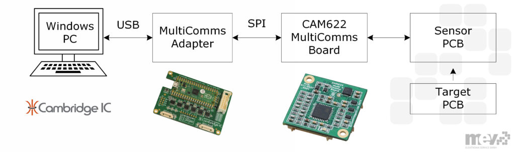
CAM622 MultiComms Board: including the CAM622 processor and supporting SPI, BiSS-C, SENT, and quadrature ABN interfaces.
MultiComms Adapter: connects to a PC over USB and to a CAM622 via SPI, BiSS-C, or SENT. It allows PC-based operation of CambridgeIC CAM622 software for measurements and configuration of quadrature ABN and BiSS-C interfaces.
MultiComms Bundle: includes both the MultiComms Board and Adapter.
For evaluation purposes, MEV Elektronik offers sample sensors, targets, connecting cables, and MultiComms Bundles directly.
Significance for MEV and its customers
The addition of CambridgeIC’s Linear Sensors Type B to MEV Elektronik’s portfolio represents a strategic expansion into the next generation of inductive position sensing. For MEV, the partnership strengthens its position as a technology leader and trusted advisor to OEMs and system developers seeking high-performance, cost-effective sensing solutions.
For customers, this collaboration brings clear benefits:
Access to a proven and innovative sensing technology with outstanding precision and robustness
Simplified integration through standard PCB manufacturing processes
Reduced system cost and improved design flexibility
Direct access to local technical expertise and evaluation support provided by MEV’s experienced engineering team
Through this collaboration, MEV continues to fulfil its commitment to offering products that combine technical excellence, ease of implementation, and long-term reliability — empowering customers to design more efficient, accurate, and sustainable systems.
“With CambridgeIC’s new Linear Sensors Type B, we are enhancing our product portfolio with a truly next-generation sensing solution that combines performance, practicality, and reliability,” said Guido Gandolfo, Product Line Manager of MEV. “Our customers consistently seek technologies that deliver precision, durability, and value. CambridgeIC’s new sensors meet these expectations perfectly. This partnership further reinforces MEV’s role as a reliable technology partner and provider of innovative sensor solutions.”
Availability & Outlook
The CambridgeIC Linear Sensors Type B are available now. MEV Elektronik offers samples, design kits, and comprehensive support for initial testing and integration.
About Cambridge IC
CambridgeIC, founded in 2007, develops processor ICs for resonant inductive sensing technology. The team has been pioneering this technology since 1994 and today serves a wide range of customers in industrial, medical, and automotive applications, including market leaders in their fields.
BLDC motor IC with HFI for impressive low-speed torque with sensorless FOC.
MEV presents the FU6866 BLDC controller IC from Fortior Technology. It integrates state-of-the-art High Frequency Injection (HFI) technology to ensure high torque even at low speeds, setting new standards in motor control applications.
HFI (High Frequency Injection)
HFI technology allows for precise rotor position determination using high-frequency signals, even with very little or no movement. This means:
Higher torque at low speed – ideal for applications where the motor is operated under load from standstill
Reliable sensorless startup at heavy loads
Robust sensorless control even where conventional methods (e.g., back EMF) do not provide sufficient signal evaluation
Stable control and smooth transition between standstill and motion
Reduced sensor hardware requirements – because the rotor position can be obtained directly through the injection process
Thanks to this feature, the FU6866 is particularly suitable for torque-critical applications during start-up, for systems with frequent changes between standstill and movement, and for compact motor controller solutions where additional sensors are impractical.
Technical highlights & features
In addition to HFI, the Fortior FU6866 offers the following outstanding technical features
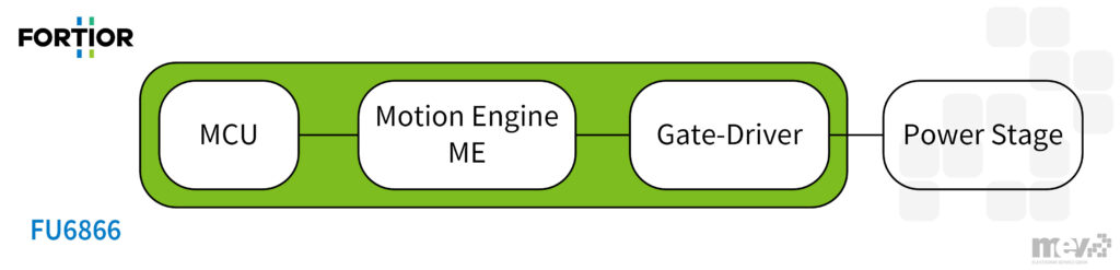
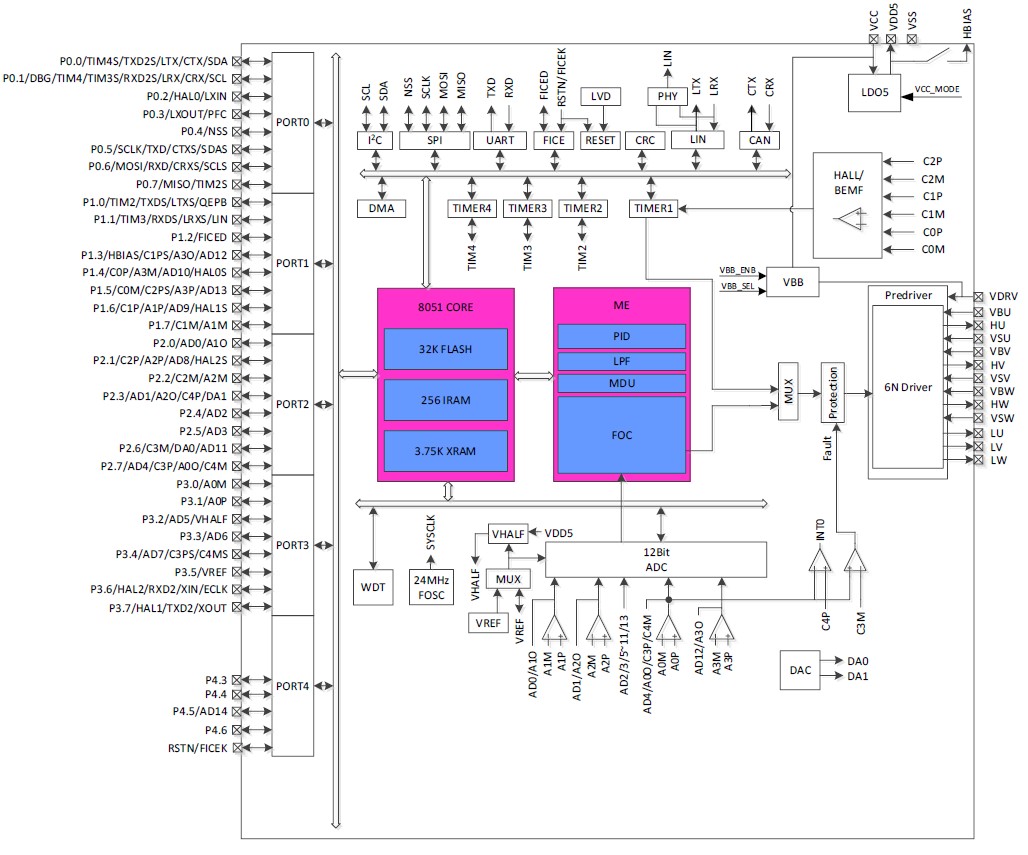
Dual-core architecture: Combination of a motor engine core (ME core) for real-time control and an MCU-core for application and system control
Integrated 180V pre-driver: Direct control of external N-channel MOSFETs
Supported control methods: FOC (Field-Oriented Control), trapezoidal and sine PWM, with and without sensors
Analog and digital peripherals: 12-bit ADCs, PGAs, comparators, DACs, timers, PWM generators
Communication interfaces: SPI, I²C, UART, LIN, CAN
Flash memory: 32 KB with CRC integrity check
AEC-Q100 Grade 1 certified: suitable for automotive applications
Supply: 6,5 – 18 V, internal LDO + up to 180V for driver
Package: QFN-56 (7 × 7 mm)
The combination of advanced control technology, HFI capability and high integration makes the FU6866 a powerful alternative to conventional motor control solutions.
FU6866 Block Diagram
Significance for MEV and its customers
By expanding its Fortior portfolio with the FU6866, MEV Elektronik is strengthening its position as a full-service provider for modern engine control solutions. Customers benefit from:
Innovative technology from a single source – from design support to supply
Access to the latest engine control ICs, especially for demanding, torque-critical applications
Technical advice and application support from MEV’s experienced engineers
“The Fortior FU6866 opens up new possibilities for BLDC motor control,” says Guido Gandolfo, Product Manager at MEV Elektronik Service GmbH. “Thanks to HFI, the rotor position can be measured even at extremely low speeds – without the need for additional sensors. This means higher efficiency, more compact designs, and cost savings.”
Availability & Outlook
The Fortior FU6866 is available now. MEV offers samples, design kits, and comprehensive support for initial testing and integration. With this expansion, MEV underscores its commitment to consistently incorporating cutting-edge technologies into its portfolio and enabling customer solutions with real competitive advantages.
About Fortior Technology
Fortior Technology (Shenzhen) Co., Ltd. is a leading provider of integrated circuits and system solutions for motor control, drive technology, and power electronics. The company develops and manufactures high-quality motor control ICs, gate drivers, digital signal controllers, and ASICs for applications in industry, automation, household appliances, power tools, and automotive.
With a focus on efficiency, precision, and integration, Fortior offers customized solutions for BLDC, PMSM, servo-, and stepper motor applications. The products are characterized by high reliability, robust protection mechanisms, and outstanding control performance – and are used by leading OEMs worldwide.
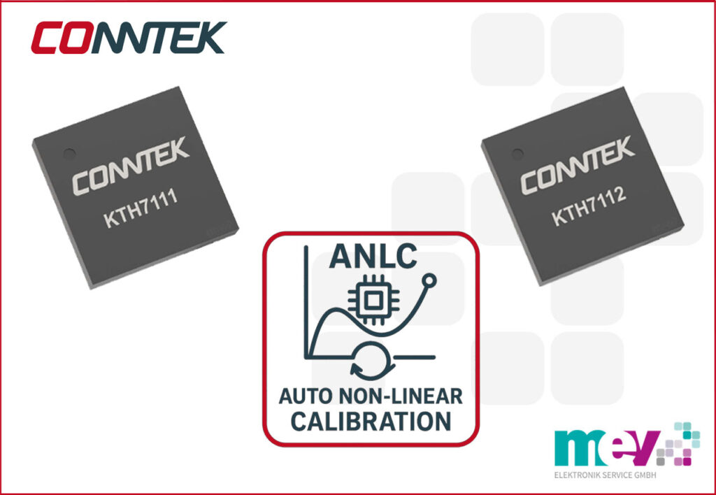
16-bit hall magnetic angle sensor ICs with automatic non-linear calibration (ANLC) and low error.
MEV introduces the Conntek KTH7111 and KTH7112 encoder ICs. Both devices set new standards in precision and ease of integration thanks to patented Automatic Non-Linear Calibration (ANLC) technology, which automatically compensates for mounting and magnet variations, ensuring exceptionally high accuracy.
The ANLC feature is the heart of Conntek’s new encoder generation. While traditional magnetic angle sensors require external calibration procedures or host-side computation, the KTH7111 and KTH7112 perform the compensation fully automatically within the sensor.
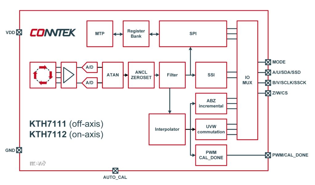
KTH7111 supports off-axis topology, while KTH7112 is optimized for on-axis applications.
Automatic measurement and error correction: The module records 16 measuring points over a complete revolution, determines deviations in the magnetic field line and calculates compensation parameters internally.
No external calculation or firmware routines required: all analysis and storage are done on-chip.
Outstanding accuracy after calibration achieving INL < ±0.1° (KTH7112) and INL < ±0.2° (KTH7111).
Calibration status display via PWM signal (50% = calibration, high = successful, low = failed attempt).
This makes the installation of magnetic encoder systems significantly easier, more robust and more precise – even with mechanical tolerances or off-axis mounting.
Additional Highlights
Ultra-low output noise (0.015° rms)
Supports ABZ incremental output up to 16,384 steps/rev
UVW commutation for 1–32 pole pairs (BLDC compatible)
Configurable PWM frequency (120 Hz – 3.8 kHz)
Flexible interface configuration via SPI and MODE pins
On-axis and off-axis magnet compatibility
KTH7111 & KTH7112 Block Diagram
Benefits for System Designers
Thanks to the integrated ANLC feature, both encoders dramatically simplify production and calibration workflows while improving accuracy and robustness.
Automatic and precise alignment compensation
No external calibration hardware or software required
Reduced assembly tolerance demands and manufacturing cost
Consistent accuracy across temperature, voltage, and aging
Optimized for motor control and robotics applications
Expert Insight
“With ANLC, Conntek brings real intelligence into hall-magnetic sensing,” says Guido Gandolfo, Product Line Manager at MEV. “The KTH7111 and KTH7112 eliminate the need for external calibration hardware or complex software routines — the sensor simply calibrates itself. This not only improves precision but also saves valuable development and production time for our customers.”
MEV – Your partner for Conntek sensor technologies
As an authorized Conntek / KTsense Microelectronics distributor, MEV Elektronik Service GmbH provides full support for the new KTH711x series sensors, including:
Samples and evaluation boards
Application and design-in support
Guidance for motor control, encoder integration, and calibration setup
Reliable logistics and technical assistance for series projects
Availability and Outlook
The new Conntek KTH7111 and KTH7112 as well as the corresponding evaluation kits are now available from MEV.
KTH7111 and KTH7112 will be presented at Embedded World show in Nuremberg (10 MAR to 12 MAR 2026) at the MEV booth 153 in hall 3. Experts from the manufacturer Conntek are on site. You are welcome to book an appointment in advance.
About Conntek / KTsense Microelectronics
Conntek (a brand of KTsense Microelectronics, Quanzhou, China) develops high-performance magnetic position sensors and encoder ICs for industrial and automotive applications. By combining advanced analog front-end design with digital signal processing and innovative calibration algorithms, Conntek provides precise, reliable, and easy-to-integrate magnetic sensing solutions for modern motion control systems.